Week 1
Goal- Learn the basics of soldering, electrical safety, and electricity.
Process- I completed the "Intro to Soldering" assignment and read through the first 10 assigned pages of the Safety Chapter within the "All About Circuits" eTextbook.
Reflection- I learned that there are different types of wires, that serve of conductors, that influence the current within an electrical circuit. I also learned about the process of using the soldering iron, actually soldering something on a board, and the importance of tinning the tip of the soldering iron. I learned what bad soldering joints looked like and how to make good ones. From the eTextbook, I reviewed the basics of Ohm's law, which is the principle that current equals voltage divided by resistance. I also learned about the numerous electrical hazards and physiological effects. For instance, electrical current has the potential to cause severe burns due to power dissipation. I also learned that muscles can involuntarily contract, which is called tetanus. I also learned about shock current path and how people get shocked by electricity. I was also introduced to the multimeter, which is used measure thing such as voltage, current, and resistance. Lastly I learned that the common sources of electrical hazards are wet conditions and power lines.
Week 2
Goal- Go more in depth with the basics of electricity and start building circuits.
Process- I looked through the "Basics of Electricity" and the "Volts, Amps, & Ohms" presentations. I also looked up some soldering tips for beginners. Lastly, I started going through a packet and building circuits that are depicted in the pictorial and schematic diagrams in TinkerCAD.
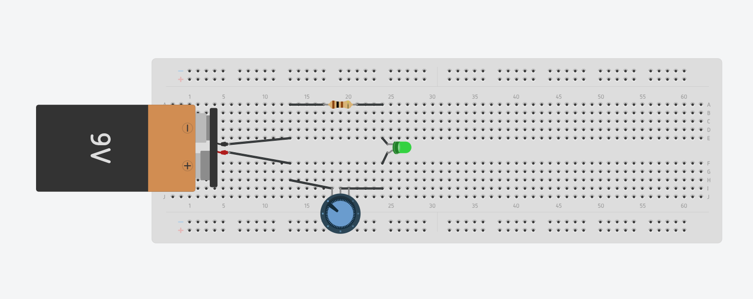
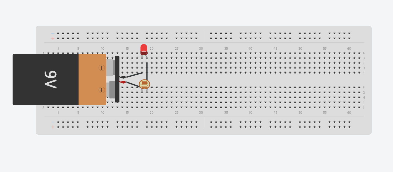
Reflection- I got a little bit of review of work, energy, power, voltage, current, and resistance, which are topics I learned about in Honors Physics. Work is the exertion of a force to overcome resistance. Energy is the ability to do work (electrical, mechanical, light, chemical, nuclear, and heat/thermal). Power is the amount of energy consumed per unit of time. Current is the amount of electrons flowing within a circuit. Voltage is the force behind the movement of electrons. Resistance is the opposition to electron flow within a circuit. I also reviewed the basic components of a circuit (power source, load, conductors, and control device) and conductors, insulators, and semiconductors. The tips that I looked up consisted of not moving the joint while it is cooling and not applying too much pressure. The circuits I did involved LEDs and resistors, they were basic, but I wanted to start to familiarize myself with all of the different components. The first circuit I did involved a potentiometer, which controls the brightness of the LED by turning a knob. The second circuit used a photocell, which controlled the dimness of the LED by blocking the photocell.
Process- I looked through the "Basics of Electricity" and the "Volts, Amps, & Ohms" presentations. I also looked up some soldering tips for beginners. Lastly, I started going through a packet and building circuits that are depicted in the pictorial and schematic diagrams in TinkerCAD.
Reflection- I got a little bit of review of work, energy, power, voltage, current, and resistance, which are topics I learned about in Honors Physics. Work is the exertion of a force to overcome resistance. Energy is the ability to do work (electrical, mechanical, light, chemical, nuclear, and heat/thermal). Power is the amount of energy consumed per unit of time. Current is the amount of electrons flowing within a circuit. Voltage is the force behind the movement of electrons. Resistance is the opposition to electron flow within a circuit. I also reviewed the basic components of a circuit (power source, load, conductors, and control device) and conductors, insulators, and semiconductors. The tips that I looked up consisted of not moving the joint while it is cooling and not applying too much pressure. The circuits I did involved LEDs and resistors, they were basic, but I wanted to start to familiarize myself with all of the different components. The first circuit I did involved a potentiometer, which controls the brightness of the LED by turning a knob. The second circuit used a photocell, which controlled the dimness of the LED by blocking the photocell.
Week 3/4
Goal- Start to model more complex circuits on TinkerCAD
Process- I continued to model each circuit in the packet in TinkerCAD and using physical components.
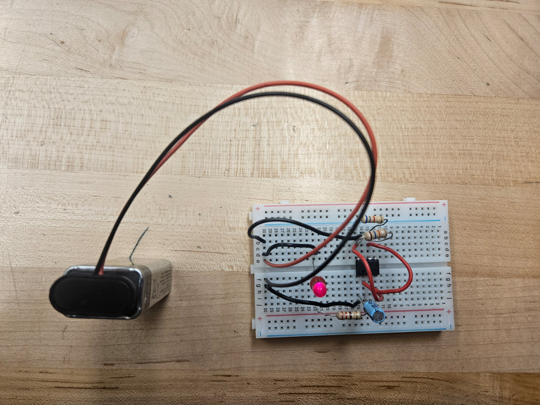
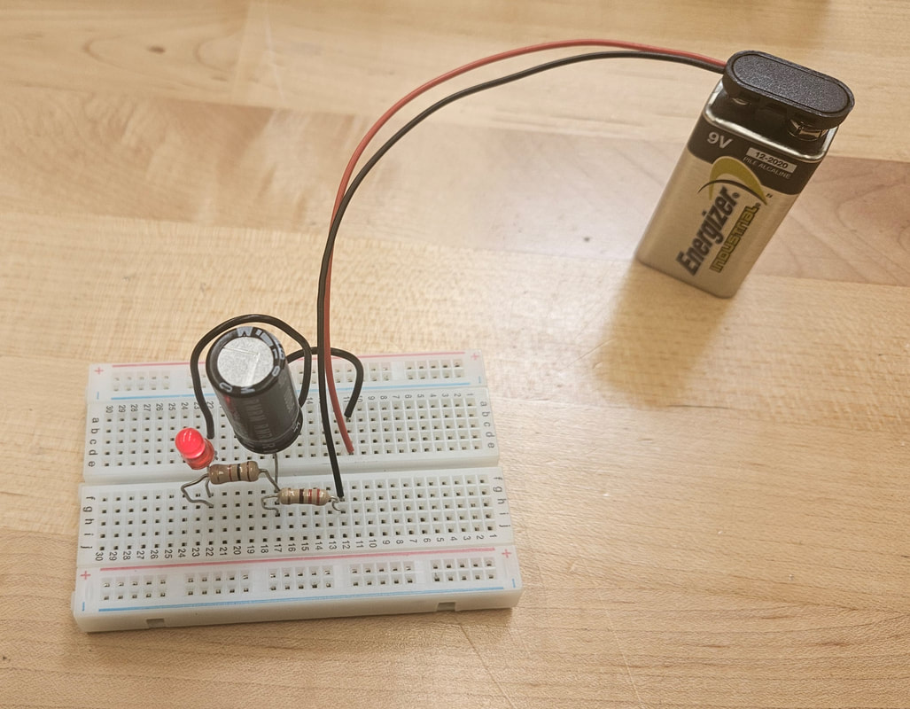
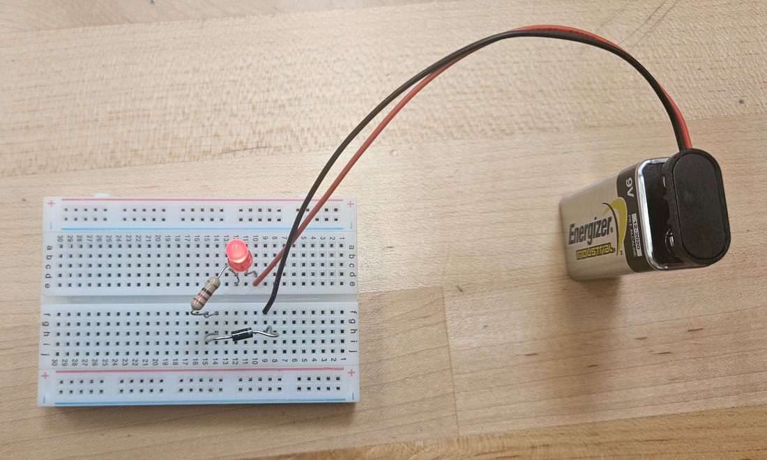
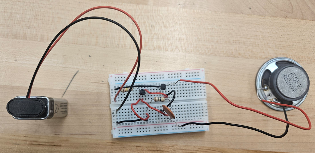
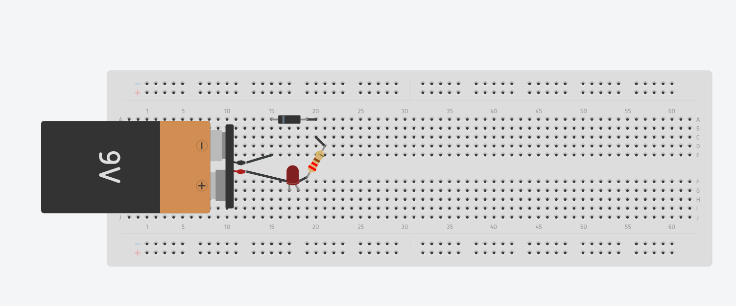
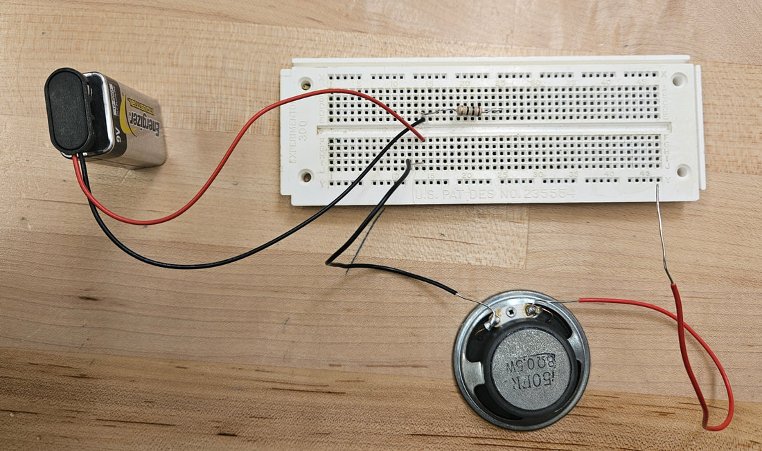
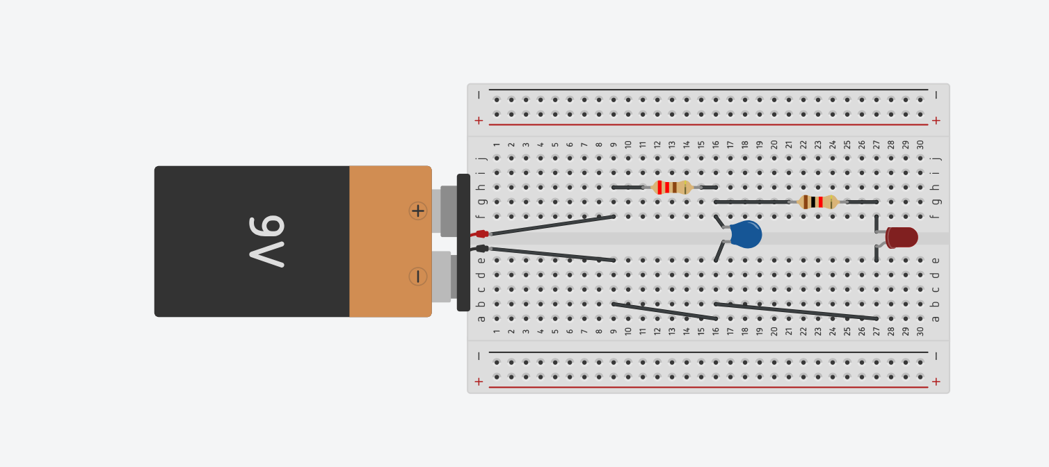
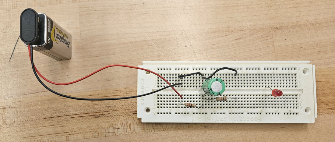
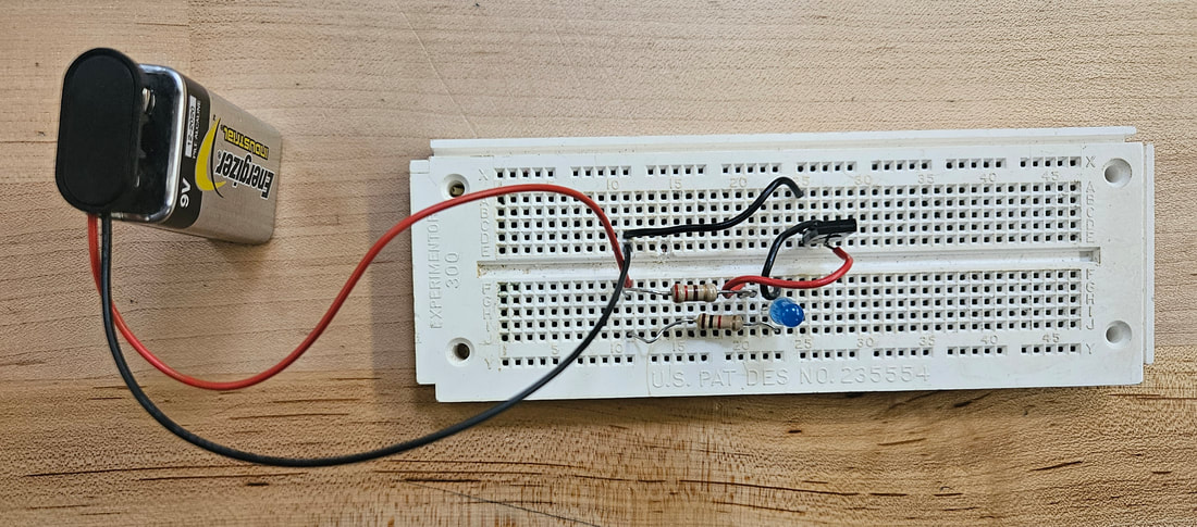
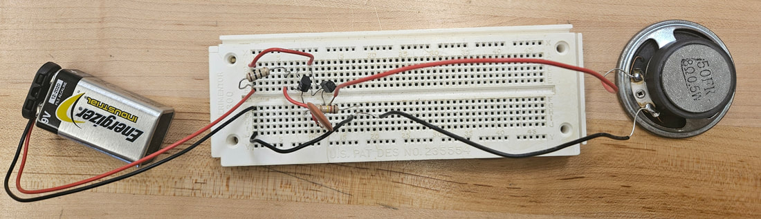
Reflection- The circuits I built included a diode, which allows electrons to flow in one direction, a speaker, which converts electrical energy to sound energy, and a capacitor, which stores electric energy within a circuit. I tried to finish modelling the circuit that had a speaker, but TinkerCAD did not have a speaker. It instead had a piezo, which is a type of buzzer that makes sounds at different frequencies. Instead of using TinkerCAD, I just modeled it physically. Every time I touched the red speaker wire to the resistor, the speaker made sounds, effectively converting electrical energy to sound energy in the form of sound waves. The capacitor stored electric energy when the batter was connected and allowed the LED to light up when the battery was disconnected. The electrons were basically being saved for later in case the power supply was disconnected from the circuit.
Process- I continued to model each circuit in the packet in TinkerCAD and using physical components.
Reflection- The circuits I built included a diode, which allows electrons to flow in one direction, a speaker, which converts electrical energy to sound energy, and a capacitor, which stores electric energy within a circuit. I tried to finish modelling the circuit that had a speaker, but TinkerCAD did not have a speaker. It instead had a piezo, which is a type of buzzer that makes sounds at different frequencies. Instead of using TinkerCAD, I just modeled it physically. Every time I touched the red speaker wire to the resistor, the speaker made sounds, effectively converting electrical energy to sound energy in the form of sound waves. The capacitor stored electric energy when the batter was connected and allowed the LED to light up when the battery was disconnected. The electrons were basically being saved for later in case the power supply was disconnected from the circuit.
Week 5
Goal- Continue to work through the electronic lab packet, completing at least 2 experiments this week.
Process- I completed the SCR Checker and the NPN Transistor Checker experiments.
Reflection- The circuits I physically built included a SCR and an NPN. A SCR, or a silicon/semiconductor controlled rectifier, is a 4-layered device that controls current. It functions as switch that can turn a small or large amounts of power on and off. The most common use for them is converting AC (alternating current) to DC (direct current), which is another way to describe rectification. An SCR is similar to a diode, the only difference is that the SCR as a gate that is used to trigger the SCR to start conducting current. A NPN (negative-positive-negative) transistor is a device that is used to amplify circuits. It can amplify weak signals and are used in devices that require a current sink. It is a specific type of bipolar junction that contains a P-type (positive) semiconductor that is placed between two N-type (negative) semiconductors.
Week 6
Goal- Continue to work through the electronic lab packet, completing the last 3 experiments.
Process- I completed the PNP Transistor Checker, Transistor Oscillator, and Blinking Light experiments.
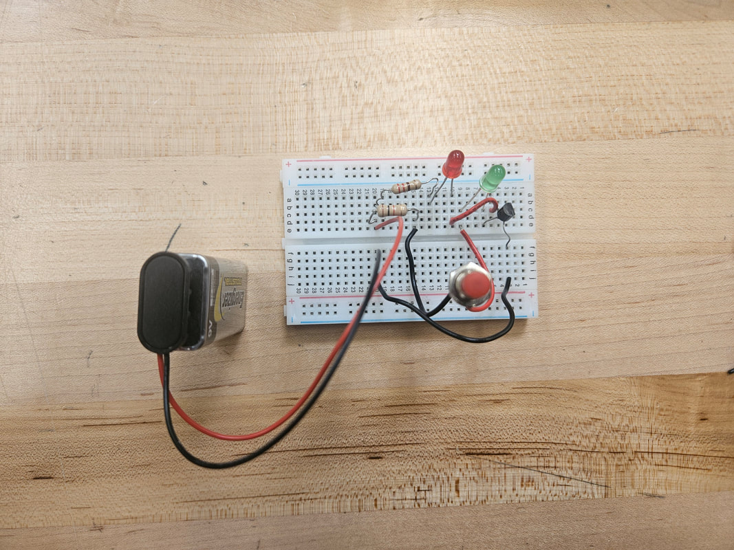
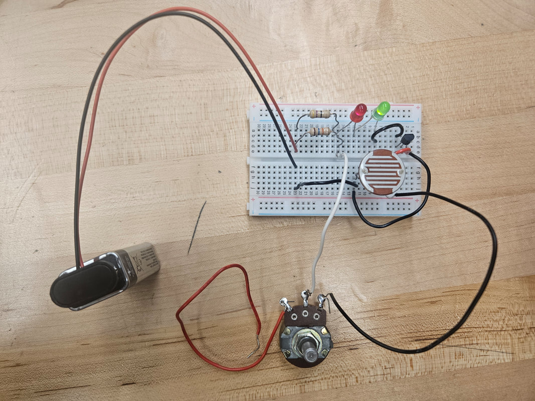
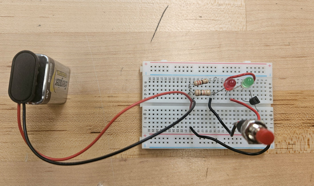
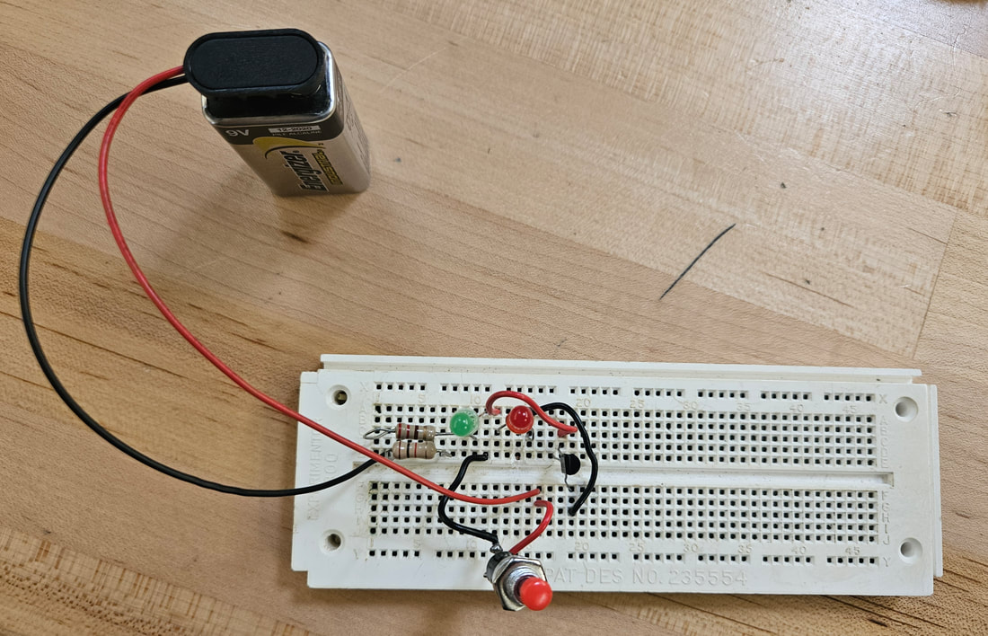
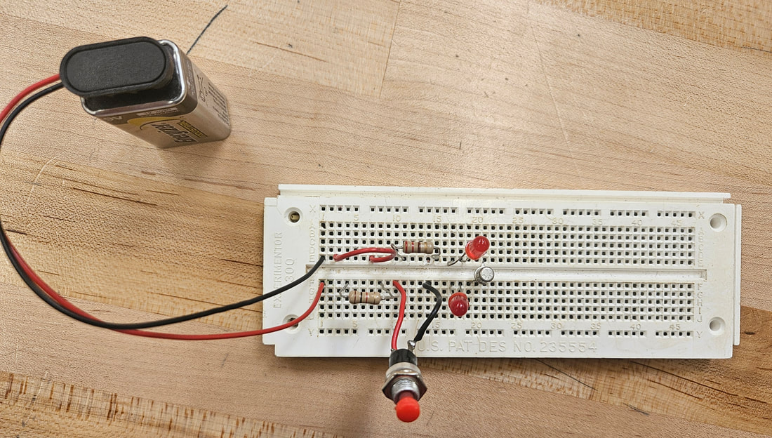
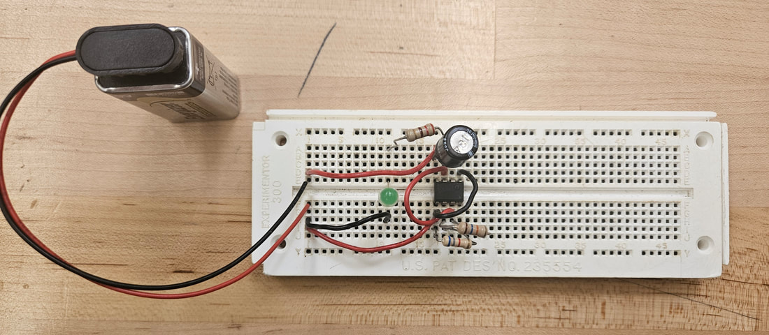
Reflection- The last 3 circuits I built included a PNP transistor, an oscillator, and a 555 IC timer. I learned that a PNP transistor is similar to a NPN transistor. The only difference is the way the order and amount of positive and negative diode terminals. The PNP has a positive-negative-positive diode order and is also used as a switch or amplifier within a circuit. It can amplify the flow of current but in the opposite direction when compared to a NPN transistor. It can also be used to turn an electric device on and off digitally. Both transistors have an emitter, base, and collector, each has its own calculated value of current flow. An oscillator is a device that causes a periodic fluctuation in current within a circuit, or alternating current. The periods of fluctuation can represented using a sine wave, square wave, or a triangle wave. The primary use of an oscillator is to convert direct current to alternating current so it can be used to set frequencies, for audio, or clocks. An example is the pendulum within a clock. A 555 IC timer, or an integrated circuit timer, is an electronic device that allows for precise timing and schedule of events. It is commonly used in industrial automation, home appliances, and personal devices. It comprises three 5K ohm resistors that are used for dividing its voltage. In addition to building the last 3 experiments, I built an extra one of my choosing, which as the automatic night light. This circuit included a potentiometer, photocell, 2 resistors, 2 LEDs, and a NPN transistor.
Process- I completed the PNP Transistor Checker, Transistor Oscillator, and Blinking Light experiments.
Reflection- The last 3 circuits I built included a PNP transistor, an oscillator, and a 555 IC timer. I learned that a PNP transistor is similar to a NPN transistor. The only difference is the way the order and amount of positive and negative diode terminals. The PNP has a positive-negative-positive diode order and is also used as a switch or amplifier within a circuit. It can amplify the flow of current but in the opposite direction when compared to a NPN transistor. It can also be used to turn an electric device on and off digitally. Both transistors have an emitter, base, and collector, each has its own calculated value of current flow. An oscillator is a device that causes a periodic fluctuation in current within a circuit, or alternating current. The periods of fluctuation can represented using a sine wave, square wave, or a triangle wave. The primary use of an oscillator is to convert direct current to alternating current so it can be used to set frequencies, for audio, or clocks. An example is the pendulum within a clock. A 555 IC timer, or an integrated circuit timer, is an electronic device that allows for precise timing and schedule of events. It is commonly used in industrial automation, home appliances, and personal devices. It comprises three 5K ohm resistors that are used for dividing its voltage. In addition to building the last 3 experiments, I built an extra one of my choosing, which as the automatic night light. This circuit included a potentiometer, photocell, 2 resistors, 2 LEDs, and a NPN transistor.

Week 7/8/9/10
Goal- Improve my breadboarding skills.
Process- Rebuild some of the previous circuits that didn't light up/ did not work. I rebuilt the Storage of Electrons, Diode Tester, SCR Tester, NPN Transistor Checker, PNP Transistor Checker, Transistor Oscillator, Blinking Light, and Automatic Night Light.
Reflection- I wanted to take my time rebuilding these since I felt I was sort of speeding through these so I could learn about the different electrical components. I did not move on to the next one until the one I was working on fully worked, which what I should have done the first time. By taking my time with each circuit, I have come to understand breadboarding a lot more than before I started my independent study. Taking this independent study further improved my knowledge in breadboarding and the different electrical components.