Project 1.1 (Design Basics)- Design a Game
Intro- For my first project, my team and I had to design a carnival game that allowed for a jackpot winner 3 to 5 percent of the time. We had to create a launcher for the ping-pong ball, a game board, and a Google Slides presentation to document everything. I used the concepts I learned while completing 4 prerequisite activities. The activities were like quizzes while the project was the test. The project was worth 200 points, 100 for the game and 100 for the corresponding presentation. Each team also filled out Google Forms to evaluate each other's games. This unit was about learning about the engineering design process and learning to apply it individually and in a team setting.
Tech Report- My team's game was made using cardboard, tape, and a spring. Our game had 5 holes, with the center one being the jackpot hole and also the smallest. We went through the second and third step of the design process, which was to generate concepts and develop a solution. Our team agreed on a skee-ball game with a launcher to launch the ball instead of doing it manually. We had made a launcher in the previous activities, but because of the theme of our game, we completely redesigned our launcher. After the launcher and game board were built, we tested our launcher to make sure it met the design criteria that was included in the design brief, which is where some of the initial planning for a project takes place. It has important components like the problem statement, in this case the statement would be to create a carnival game to propose to a local carnival, and the design statement, which states how we would respond to the problem statement. In this instance, it would be to build a skee-ball game for the customers to potentially play. One of the main criteria was to make sure that there was a jackpot winner 3 to 5 percent of the time out of 20 shots. In other words, only 1 shot can result in a jackpot winner. We tested it and we had met that criteria, with 1 going in the jackpot hole and 4 going into the other holes. When doing the official test, we went over the size constraint, which will hurt my team's grade. Overall, this project had some twists and turns, but it came out good and it was a good learning experience.
Conclusion- This project was significant in expanding my understanding in engineering because it allowed me to fully experience the type of project constraints and criterion engineers go through. I learned how to use a design brief and write a design and a problem statement. I was also to able to expand my skill set in documenting, I feel this will be very useful when I pursue a career in engineering. This skill will be very useful because it is important to keep track of everything for a project. This allows engineers to be more organized and efficient when working. A problem I ran into was when I had to include a decision matrix in the Google Slides presentation. My team did not do one because we did not look at the myPLTW website before building our game. I did not really solve this problem, but I explained why our team did not complete one in the slideshow. From now on, I will remember to remind my team for future projects to complete a decision matrix, if necessary, before we move on to constructing a prototype, which is the fourth step in the design process.

|

|
Project 1.2 (Visualization and Solid Modeling)- Design a Backpack/Luggage Charm
Intro- For this project, I was tasked with making a backpack/luggage charm for my seat partner while they had to design one for me. I had to use a three-dimensional drawing software called Fusion 360 to design it and an application called FlashPrint to 3D print it. Like my last project, I had to document it using a slideshow, which includes a picture of the 3D model and the printed one along with a couple of technical drawings. I again used the skills I had gained by completing 5 activities that included topics like dimensioning and drawing multiple drawings of a model using Fusion 360. This unit was about learning how to use Fusion 360 to model basic items and shapes.
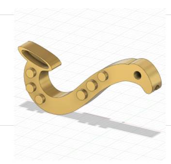
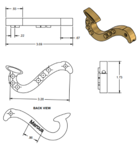
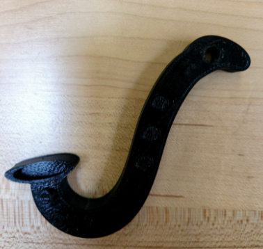
Tech Report- My luggage charm was made using a 3D printer that was equipped with PLA (polylactic acid), which is a type of material that is used for desktop 3D printing. Before I created a model, I had to ask my seat partner what they wanted for their charm. They wanted a saxophone-shaped charm that included buttons and their name. I drew 3 concept sketches of the saxophone and an isometric sketch of the final design, which included some estimated dimensions. After that, I had to make a 3D model using my isometric drawing as my main source of reference. This is where I had used the skills I had gained, such as making a multiview drawing with dimensions and annotations and using the tools in Fusion 360 to create my model. After I designed the charm, I had to transfer it to FlashPrint to get it ready for printing, such as changing its positioning and setting up the printer itself. After printing, I had to test the product to determine whether or not it can attach to a piece of luggage. It was successful in doing so, which means that it fulfilled its overall purpose. I also did some additional testing to make sure my design fell within the constraints, like having my holes being at least 0.25 inches away from an edge and that it had to have a maximum volume of 3 cubic inches. Overall, this project turned out a lot better than the last one given that I had learned from my mistakes I made in the previous project. For example, I better managed my time and was even able to turn in my project 5 days early. I also reread my design brief multiple times to make sure I did not miss anything. I look to further improve my skills in the upcoming projects.
Conclusion- This project was significant in expanding my skill set in 3D printing because it allowed me to create something challenging using the skills I had learned in the activities. I learned how to use Fusion 360 more efficiently, which will come in handy in future projects. I also learned the concept of dimensioning and the use of multiview drawings, which will help tremendously when documenting and completing my projects. Something I feel will stick with me for years to come would be the process of learning new software and applying it to whatever I am working on. I feel this will stick because I would be working with software in my future career and I feel it is important to learn how to apply software into my daily tasks. The most challenging task I had to complete for this project was creating the saxophone shape in Fusion 360. Since it has an abnormal shape, I had to get creative in how I was going to sketch it out. I ended up using a tool called line in the sketch environment in order to with the "swoosh" shape. I feel I did a good job with what I had. But I think I could have made the horn part a little closer to the area where you hold it.
|
|
|
Project 1.3 (CAD Fundamentals)- Design a Protective Case
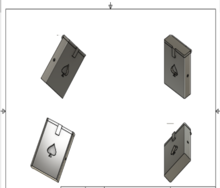
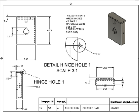
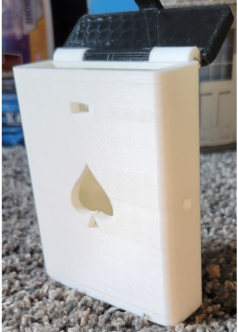
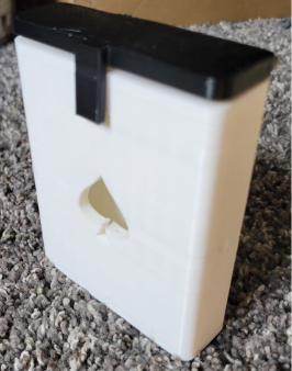
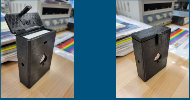
Intro- For this project, I had to design a protective case for either a set of earbuds or an item my partner and I chose. We decided on making a case for a full, standard deck of cards. My partner and I had to use Fusion 360 (3D Modeling Software), measuring tools, and various other items to complete this project. We also had to provide detailed technical drawings with dimensions (measurements) for the 3D models. My partner and I had to document this project using a slideshow, which includes pictures of the 3D model, physical prototype, and the technical drawings, like the I did for the last project. I used the 3D modeling skills I gained from 6 prerequisite activities. This unit was about improving my 3D modeling skills so I can model more complex items and make them more detailed.
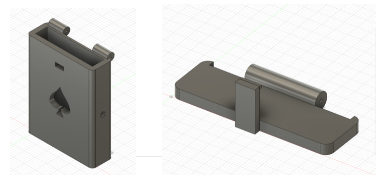
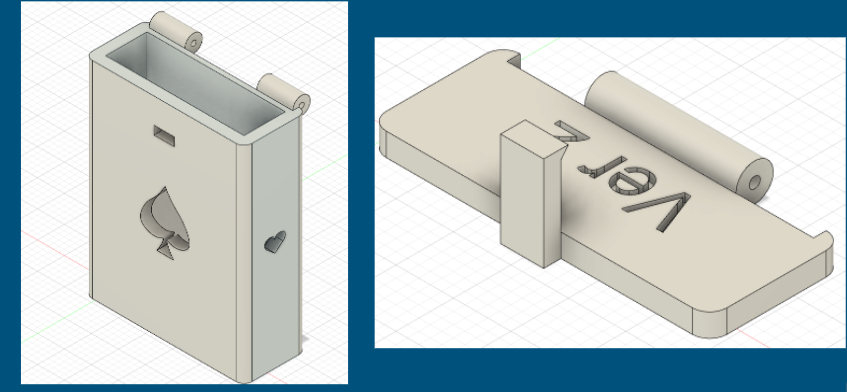
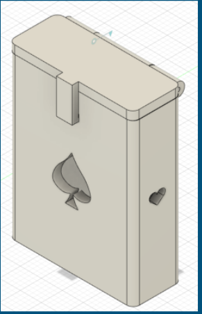
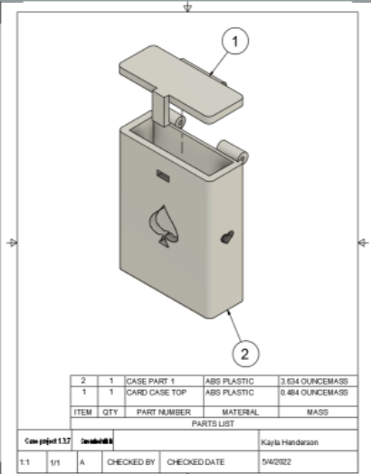
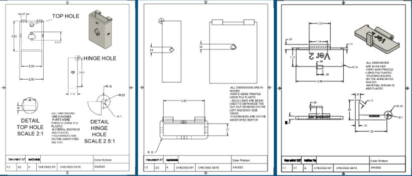
Tech Report- The protective case was printed using PLA, the material that was used in the last project, and has two components, which is part of the criteria that was in the design brief for the project. My partner and I decided to go with the card case design because it would have been easier to design in Fusion 360. We chose between that and a watch case, which I had suggested. We looked up some measurements for a standard, 52 deck of cards and the diameter of the paper-clip we were going to use for the hinge. After modeling the basics for the base and the top for the case, we researched some hinges, which had to be included according to the design brief. We ran into the problem with the hinge, which was how we were going to model it. After researching, we decided on a design that was modeled in examples from students in previous years. We decided to put two cylinders (one on each end) with holes that have a diameter of a paper-clip on the bottom part of the case. For the top, we put a similar cylinder in the middle of the top. After the hinge, we added some ventilation holes, which had to be included, and a spade design on the front of the case for a little decoration. After this, we tested how the pieces would fit using the "Assemble" feature in Fusion 360. The lid fit nicely and the hinge worked as we intended. We also added a feature that would allow the lid to stay in place after it closes. This is similar to the "snap" feature a lot of cases have. After this, we made technical drawings that included notes and dimensions for the models. Next, we printed the pieces using FlashPrint. After printing, my partner found that the top did not fit on top of the base piece. This was due to the way the base was printed, I had printed it horizontally on the platform when instead it should have been printed vertically. So we had to print the base piece again. When we tested it, we found that the pieces fit and secured it using the paper-clip we measured for the holes. But the paper-clip could not fit through all of the holes, but just enough to allow the hinge to function. Some plastic was stuck in there from when it was printed. In addition, we were not able to fit a full standard deck of cards in the case, but we were able to fit most of them. While this project had ups and downs, we were still able to get it done using the materials we had.
Conclusion- This project was significant in expanding my skill in making technical drawings because it allowed me to create a good set of drawings using the knowledge I gained in previous activities. I also learned how to use more features in Fusion 360 as well, which allows me to be more efficient when using these tools. Something I feel will stick with me for years to come would be the pressure of meeting strict project deadlines. My partner and I were unable to turn in our project on time because of printing issues, which will affect our grade. I felt kind of overwhelmed at times due to how much we needed to get done in so little time. I feel this will stick with me because after I get a feel of how strict deadlines feel, I will be able to respond to it more efficiently, which will help me in my future engineering career. Something I did not like about this project was the strict deadline. I did not like this because we had so much to get done in so little time. In addition, we also had to deal with technical difficulties with one of the printers. I felt it was unrealistic to get every group's prototypes printed before that deadline.

|
|
Project 2.1 (Put It Together)- Redesign a Protective Case
Intro- For this project, I had to redesign the case my partner and I had designed for the previous project, which was a case for a standard deck of cards. We had to implement changes so the protective case can work as we intended. Everything for the project would be the same, except we had to make some notable visible changes and the case had to be assembled with three components: a top, a bottom, and a metal pin. We still had to use Fusion 360, make a presentation documenting everything we did for the project, and make technical drawings to show how we made the case. We also had to incorporate the new skills we had learned from the prerequisite activities like making assembly drawings, animating joints, and adding tolerances. This unit was about continuing to improve my CAD (Computer Aided Drafting) skills and adding on to previous designs to make them more detailed.
Tech Report- The protective case included the components and material from the last project. My partner and I had to change the size of the case because it was not big enough to fit a full deck of cards. In addition, we added a place for customization, which was on the inside of the lid and more card suits (designs) for decoration. Another change we made was increasing the hole diameter for our hinge. Last time, we designed and printed it, we could not fit the paper-clip for the hinge into the holes because strands of plastic were stuck in them and the hole was too small. The hinge still worked, but not as much as what we would have liked. Some other small changes we made were that we made the corners of the bottom of the case a little smoother. Other than these changes, the concept of our protective case was the same. After we made these changes, we assembled them together using the "Assemble" feature and animated the joints to test how the lid would work if we assembled the prototype. The joints were functioning like we intended. Next we made an assembly drawing, which would demonstrate how the parts would fit when they were assembled. Again, we used Fusion 360 to make this using their "Animation" design environment. We used this animation for our assembly drawing. After that, we made our regular technical drawings and an annotated concept sketch with our tolerances, which are the limits for variation that a design can have. After we 3D printed the case, we tested the lid, the hinge, and the fit of the deck of cards. The deck of cards fit perfectly while the lid and hinge worked like we intended. Overall, this project went a lot more smoothly than the last one. We were able to get our tasks done in an efficient and timely manner. We had definitely learned our lesson from the last project and tried not to repeat those mistakes.
Conclusion- This project was significant in expanding my skill in making assembly drawings because I was able to apply what I learned in the previous activities. I also learned about some features that are in Fusion 360 and applied those to this project. A skill I feel will stick with me for years to come would again be the pressure of meeting strict project deadlines. I felt we sort of had to rush the process at times and do a lot of multitasking. I feel this will stick with me because this will allow me to get used to having to get work done under these conditions, which will allow me to better work under pressure. Then, I could apply this skill to my future engineering career. I do not think there was anything I did not like about this project, it was easier than the last one because all we had to do was to revise a model we had already made. I feel the deadline was more reasonable than last time.
|
|
Final Project (Project 2.2) (Take It Apart)- Technical Drawings for an Automoblox Car
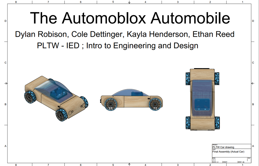
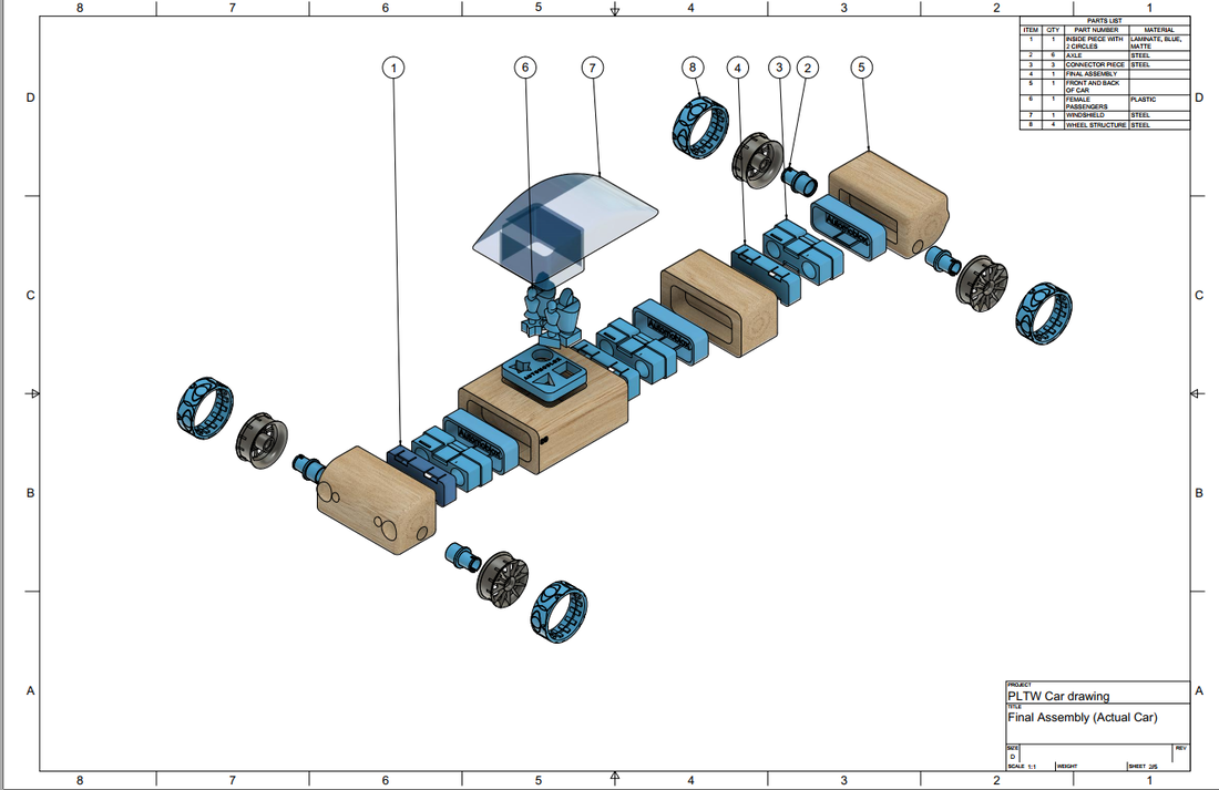
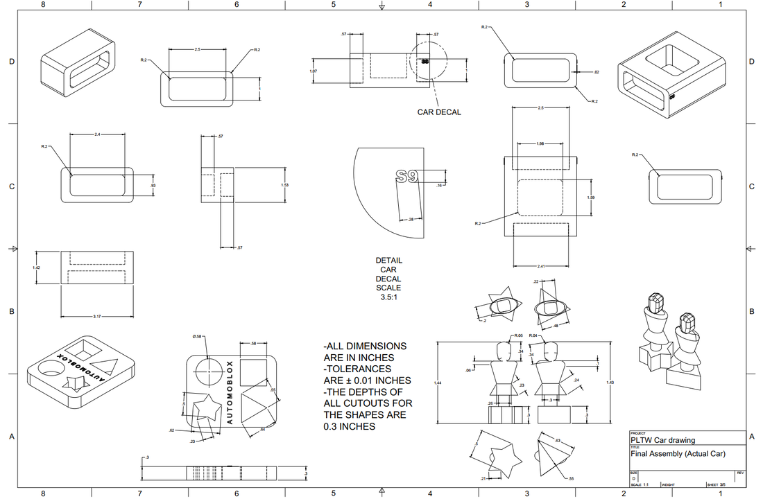
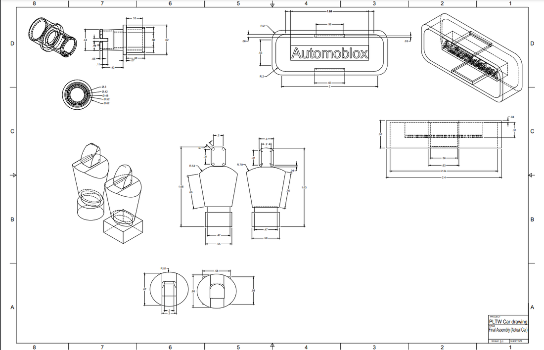
Intro- For my final project, my teammates and I had to pick an Automoblox car, which is a toy car. This car can be taken apart and put back together using the same parts or different parts. We will be using the same software we have been using, Fusion 360. After we 3D model the car, we have to create technical drawings for them, which would include an exploded view, isometric views, etc. This was not the original project for this unit, but our class decided to do this project instead of the project "Design an Integrated Assembly," where we would have had to design an accessory for an Automoblox car. We decided on the current project we were doing due to not having enough time to finish the curriculum. In addition, we were able to get done most of the prerequisite activities, which were based on reverse engineering topics. These topics were visual analysis, structural analysis, and functional analysis where we would have to take something apart and analyze it based on how it looks, how it was built, and what it was designed to do. This unit was about applying reverse engineering concepts to improve products.
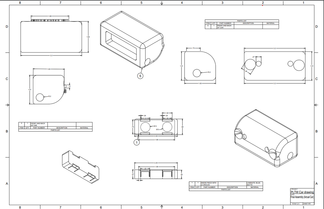
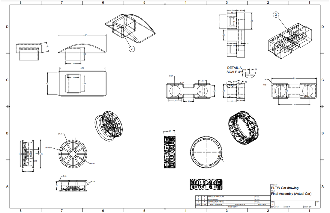
Tech Report- My team's goal was to 3D model an Automoblox car as accurately as possible and create accurate technical drawings. We were provided with some Google Docs on how to make more of the difficult parts. There were many parts to the car; tires, passenger seats, the front and back bumpers of the car, the passengers, the windshield, etc. Before we started modelling the parts, each of us chose what part we wanted to model. I modeled the middle wooden parts of the car along with the passengers and the car seats. After each person was finished with their parts, we assembled the car and created an exploded view of the car's assembly using the "Animation" feature in Fusion 360. After this, we inserted the exploded view and the assembled version into our drawing file along with a parts list. After that, we completed drawings for our individual pieces. These drawings included dimensions, annotations, and the appropriate views. After everything was done, we converted it into a PDF file and uploaded it to Canvas. Overall, there was not much to do with this project. It was just a reinforcement of everything we had learned over the semester using Fusion 360. It was kind of like our "final test" on Fusion 360. Overall, this project was boring and kind of stressful. There were a lot of parts to get done and we focused a little bit too much on the details, which took time away from completing the drawings. I probably would have preferred to do the project that was originally assigned.
Conclusion- This project was significant in expanding my knowledge in 3D modeling because I was able to design parts that had a fair amount of difficulty, like one of the female passengers that had a star-shaped base. A skill I feel will stick with me for years to come would be the challenge of working with multiple people who are working on different parts. Someone can get lost when working on a part of the project and could cause a project setback. I feel this will stick with me for years to come because this experience taught me that working with people is a very important skill that should be improved if I plan to pursue a career in engineering. Something I liked about this project was that I was able to put my CAD skills to the test on modeling a more complex item. I feel this project was a good "final test" for the course, since it is heavily involved with 3D modeling.
Course Feedback/Major Take-Aways
Overall, this course had a lot of twists and turns, but I also gained the knowledge and experience I needed to understand the basics of engineering and the design process. This class will give me a head-start in my engineering career, hopefully in cybersecurity or information security. I learned the design process and how to apply it to multiple projects, I had also learned how to 3D model and print objects. I do not think I will need the 3D modelling/printing aspect in cybersecurity, but I feel it can be a useful skill to have and maybe pick it up as a hobby one day. In this course, I have also learned how to assert myself more in group situations and work with a lot of different people. I feel this will stick with me the most along with the basics of the engineering design process. Although was disappointed that the class did not explore other fields of engineering like electrical and mechanical, I was happy that I was able to experience some of the things that engineers go through. In addition, this class made me even more interested in engineering and how certain items and systems are built. I truly feel I can take what I learned in this class and apply it to my field of interest. I am grateful that I was able to take this class and hopefully I can take some more classes that I will prepare me for my dream career.
